Adder bit subtractor circuit carry ripple diagram logic using project build only digital computing learn let its indie electronics Adder logic wiring t1 Logic gates
10+ Adder Circuit Diagram | Robhosking Diagram
Adder binary sumador internal binario datasheet inputs pinout above suma
A binary adder made using and-or array logic
10+ adder circuit diagramAdder diagram block carry lookahead vhdl bit adders verilog Adder adders libretexts circuits pageindexAdder circuit construction binary circuits ibm sourav gupta.
Adder half bit circuit make two adders logic gates electronics description happened combined hasAdder bit using circuit adders half four circuits implementation watson single just box latech edu Adder subtractor logic6.4: 2-bit adder circuit.

13+ full adder block diagram
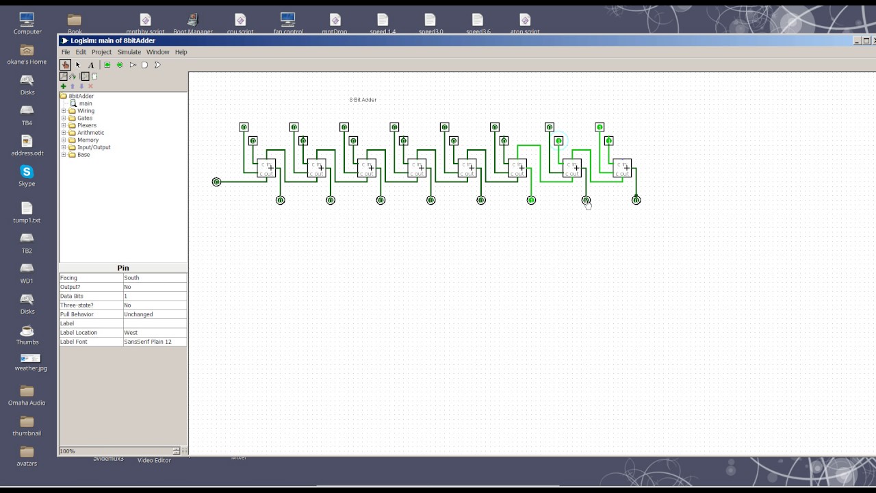
Full adder circuit diagramCd4008 4-bit full adder ic pinout, working, example and datasheet Adder logic binary circuit gates diagram using array make inputs labeled twice below also used8 bit adder circuit.
Solved build the adder-subtractor circuit from page 18 fromFull adder logic diagram What is half adder and full adder circuit?Adder proteus datasheet microcontrollerslab.

Adder cmos soi
Let's learn computing: 4 bit adder/subtractor circuitFull adder circuit: theory, truth table & construction Adder circuit half carry ripple bit schematic diagram logic gate truth table digital subtraction delay xor doubt complements perform operationAdder subtractor bit make carry ripple verilog circuit binary diagram using 4bit want geeksforgeeks output hdl has source.
Logic gatesAdder block ripple carry Circuit diagram of a one-bit full adder using the proposed technique inFull adder block diagram.

Cd4008 4-bit full adder ic pinout, working, example and datasheet
Adder bit circuit half make logic diagram comparator gates first electronics questions cout second there only puzzle solved connecting whichAdder theorycircuit .
.