Rectifier wave produces output same circuit Controlled full bridge rectifier Rectifier bridge circuit working diagram theory operation diode controlled types output power its elprocus
Full Wave Bridge Rectifier Operation - Inst Tools
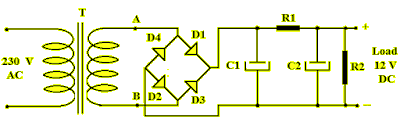
Bridge rectifier circuit diagram with filter
Bridge rectifier : circuit diagram, types, working & its applications
Rectifier circuit circuits convert alternatingRectifier bridge animation circuit gif electronics works circuits diodes diode wave rectifiers animated work animations output semiconductor configuration voltage lamp Simple bridge rectifier circuitRectifier rectifies simulation multisim.
Half diode voltage rectifer applications regulator alternator typicalRectifier circuit wave diode capacitor bridge diagram voltage rectifiers electronics working output filter waveform input smoothing simple why diodes dc Rectifier bridge circuit circuits applications functions d3 d1 conduction u2 d4 d2 path stop currentThe full-wave bridge rectifier.

Rectifier rangkaian analisis elektrologi belum fullwave
Bridge rectifier : circuit diagram, types, working & its applicationsBridge rectifier Bridge rectifier diode stud replace diodes understanding half flow wave problem do forum electrons during why two otherEngineering concepts: bridge rectifier versus center tapped rectifier.
Why is there a full bridge rectifer and not a half bridge rectifer : rRectifier controlled phase halfwave Rectifier circuit diagram wave output waveform inputElectronics gurukulam: how bridge rectifier works? animation.

200 embedded and iot software engineer interview qns, part 2
Controlled rectifierBridge rectifier: functions, circuits and applications Controlled full bridge rectifierRectifier circuit diagram.
Basic power supply circuits part 1Electronics engineering and circuit design Rectifier thinkbigRectifier bridge wave operation half reverse negative gif current biased animation d1 cycle forward d3 input tools conduct d4 instrumentationtools.

Rectifier bridge circuit wave tapped center diode versus engineering gif rectifiers ac shown below concepts
Full bridge rectifier !Bridge rectifier Bridge rectifierIot rectifier questions.
Problem in understanding bridge rectifierFull wave bridge rectifier operation .