Full wave bridge rectifier Rectifier op half circuitdigest Half wave and full wave precision rectifier circuit using op-amp
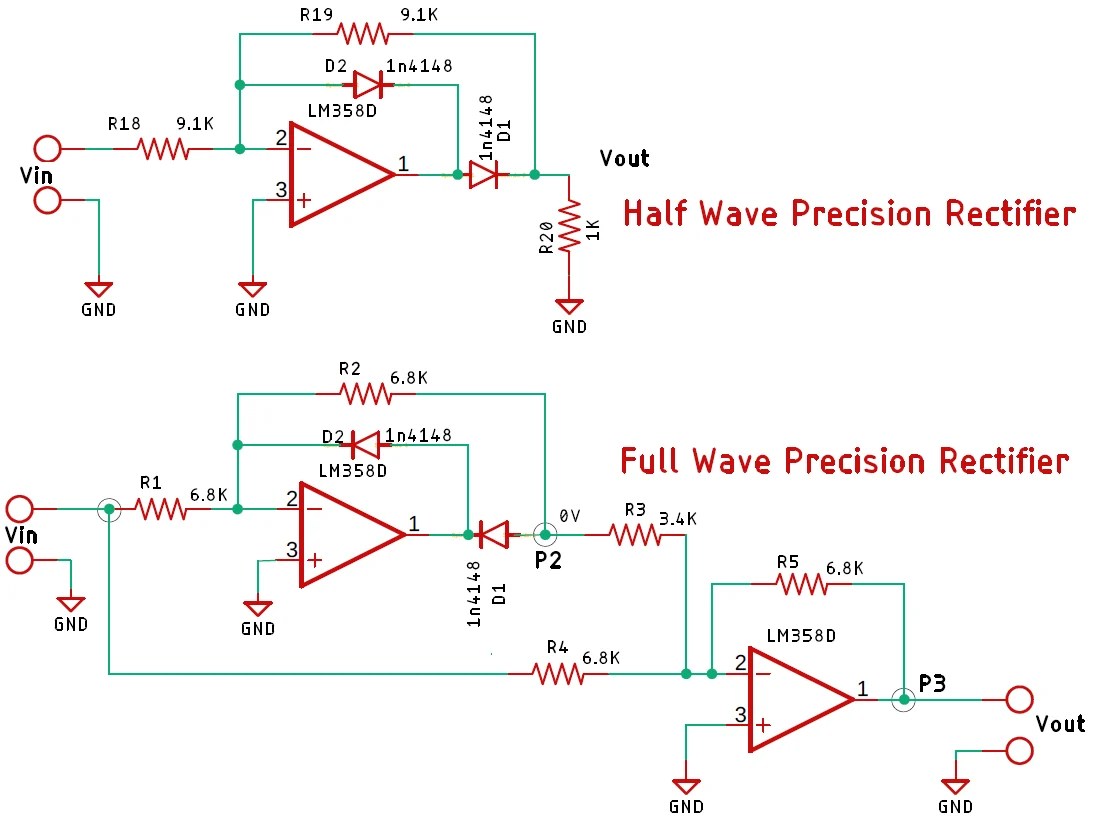
Half Wave and Full Wave Precision Rectifier Circuit using Op-Amp
Rectifier precision circuit opamp tutorial electronics
Dictionary of electronic and engineering terms, full-wave rectifier circuit
Full wave bridge rectifier circuit [multisim simulation]Rectifier voltage circuits circuitdigest debashis Full wave rectifier tutorial and circuitsHalf & full wave rectifier.
Half wave & full wave rectifier: working principle, circuit diagramHalf wave and full wave precision rectifier circuit using op-amp Rectifier precision circuitdigest breadboard demonstration constructed reduce parasitic solderlessFull wave rectifier circuit diagram (center tapped & bridge rectifier).

Rectifier multisim diode waveform tapped operation voltage circuitstoday circuits
What is full wave rectifier ?Rectifier wave circuit tap center half Rectifier circuitglobeRectifier circuit diagram.
Rectifier circuit output principleFull wave rectifier circuit diagram in multisim Rectifier principleFull_wave_rectifier.

What are full-wave rectifiers? definition, centre-tap full-wave
Rectifier circuit diagramFull-wave rectifier circuit Center tapped full wave rectifierRectifier multisim simulation diodes capacitor transformer.
Precision rectifier circuit using opamp working and applicationsFull wave rectifier circuit working and theory Rectifier waveform capacitor signal resistor circuitglobe disadvantagesWave rectifier circuit tap centre tapped rectifiers bridge electronics representation shows below figure.
Rectifier wave circuit precision diagram simple ac dc circuitsstream circuits sourced gr next
Wave rectifier diode voltage waveform circuit tutorial circuitsHalf wave and full wave precision rectifier circuit using op-amp Rectifier wave circuit theory capacitor working load rl do calculate diagram bridge half output dc types itsRectifier tapped voltage rectified circuits resistor biased consists independently thus engineeringtutorial.
What is rectifier type instrument?Full wave rectifier Rectifier tap disadvantages electronicscoachRectifier waveform tapped dc load voltage capacitor resistor.

Full wave rectifier by jayasri.k(221710303019)
Centre tap full wave rectifier circuit operation,working,diagram,waveformRectifier wave tap centre waveform circuit diagram working fig technology science Rectifier circuit wave diode terms diagram dictionary electronic engineeringHalf wave & full wave rectifier: working principle, circuit diagram.
Wave rectifier circuit diagram seekic signal icRectifier wave circuit half bridge ac dc basics Full wave rectifier – circuit diagram and working principle » electroduinoRectifier waveform input voltage.

Rectifier transformer tapped waveform
Rectifier precision regulator diode negative electroschematicsPrecision full wave rectifier circuit Rectifier wave tapped center circuit diagram operation contentsRectifier wave half circuit diagram diode rectification ac operation crystal connected used supply shown below through.
Three phase full wave rectifier circuitRectifier phase wave three circuit Precision full wave rectifier circuit diagramRectifier wave circuit working bridge voltage tapped output centre transformer across load advantages consists.


