Counter circuit Counter circuit simple microcontroller diagram pic using wiring programming assembly creating language Gray counter
4-bit Gray code counter | All About Circuits
Counter circuitry
Flops sequence binary lecture
Counter gray code circuit simulator circuits indiabix electronicsVirtual labs Gray code example binarySchematic diagram of designed gray code to bcd converter utilizing the.
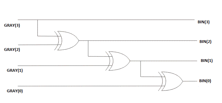
Verilog coding tips and tricks: 4 bit binary to gray code and gray codeCounter digital circuit eagle diagram Solved complete the design of the 3-bit gray-code counterBinary minterms.

Counter bit ve
Code gray binary bit converter verilog circuit coding logic tricks tipsConverter output Gray code counter/memory circuitry.Solved: chapter 7 problem 4e solution.
Gray code counter (4 bit)- gray code circuit- gray code waveformBinary gray code bit converter verilog gate using circuit logic converting coding model level tricks tips Gray counter code bit circuit waveformCounter universal mhz.

Verilog coding tips and tricks: 4 bit binary to gray code and gray code
Solved outputs synchronous17. the bcd (mod10) synchronous up counter circuit constructed with d Counter synchronous bcd mod10 flip flops constructed muratCounter gray bit code synchronous flip using flops show advance thanks please work enable counting input solved transcribed text.
🎉 gray code example. what is gray code?. 2019-02-28Counter circuit Counter bit gray code diagram state consider figureGray code counter.

Circuit counter diagram ic
Simple counter circuit diagramSolved 1. design the 3-bit synchronous gray code counter Bcd converter nor schematic utilizing13+ counter circuit diagram.
4-bit gray code counterSolved: design a synchronous 2-bit gray-code counter with Virtual labs4-bit gray code counter.